Metallography is the examination of a metal's internal structure on a prepared section. The microstructure carries the composition, the heat treatment applied, the manufacturing history and the path to failure all at once. Reaching that information depends on the section genuinely representing the material: a specimen taken from the wrong place, burnt during cutting or poorly polished will give the wrong answer however good the microscope is.
What this note covers
- Sampling: location and orientation, and the sound reference section in failure work
- Sectioning, mounting (hot and cold) and edge retention
- Grinding and polishing sequences; removing the deformation layer
- Etchant table: nital, picral, Villella, Marble, Kalling, Keller, Kroll, Beraha
- Examination techniques, choice of magnification and when to move to SEM
- Quantitative metallography: grain size, phase fraction, inclusions, decarburisation, case depth
- Recognising preparation artefacts; reporting and a practical checklist
What the Microstructure Tells You
A chemical analysis says what the material is; the microstructure says what has happened to it. Grain size, phase distribution, carbide morphology, case depth, inclusions, decarburisation and prior deformation are all read from a prepared section — and all of them are decided before the part is loaded. In failure work the microstructure is usually the evidence that separates a material problem from a service problem.
Sampling and Sectioning
In failure analysis the section is taken through the suspect area, usually perpendicular to the fracture, with an undamaged reference sample from the same part or batch for comparison. For routine quality work the location is fixed by the specification (for example, case depth at a defined position on a gear tooth). Cutting must not alter what is being examined: abrasive cutting with flood coolant is standard, while flame cutting or dry cutting destroys the very layer of interest by burning it.
Mounting
Hot compression mounting in a thermosetting resin is fast and dimensionally accurate; cold casting in epoxy is used when the material is heat sensitive, porous or fragile, and under vacuum it also fills cracks and pores so they are preserved rather than smeared. When the edge itself is the subject — coatings, case depth, decarburisation — edge retention governs: a filled resin, a nickel plating applied before mounting, or a clamped sandwich keeps the surface flat to the very border.
Grinding and Polishing
Grinding proceeds through progressively finer abrasives (typically P120 to P2500). The discipline is in two rules: each step must remove the deformation left by the previous one, and the sample is rotated 90° between steps so that remaining scratches are visible and can be tracked. Polishing continues with diamond suspensions (9, 3 and 1 µm), often finished with colloidal silica (OPS), which combines a light chemical attack with mechanical polishing and removes the last deformed layer.
The deformation layer is the central problem of specimen preparation: every grinding step introduces one, and if it survives to the end it is photographed and mistaken for the real structure.
Etching
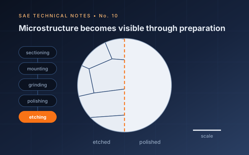
Polished and unetched, a section already shows inclusions, porosity, cracks and graphite morphology — nodularity in ductile iron is assessed in this state, and etching would only confuse it. Etching then reveals grain boundaries and phases by attacking them at different rates.
| Etchant | Typical composition | Reveals |
|---|---|---|
| Nital | 2–5% nitric acid in ethanol | General structure of steels: ferrite, pearlite, martensite |
| Picral | 4% picric acid in ethanol | Carbide and pearlite detail without attacking ferrite boundaries |
| Villella | Picric acid, HCl, ethanol | Tempered martensite, prior austenite grain boundaries |
| Kalling / Marble | CuCl2 based | Stainless steels, nickel alloys |
| Keller | HF, HCl, HNO3, water | Aluminium alloys |
| Kroll | HF, HNO3, water | Titanium alloys |
Quantitative Metallography
Numbers, not impressions, are what a report can be built on: grain size by the planimetric or intercept method (ASTM E112 / ISO 643), phase fractions by point counting (ASTM E562), inclusion rating (ASTM E45 / ISO 4967), decarburisation depth (ISO 3887), case depth (EN ISO 18203 / ISO 2639) and nodularity in cast iron (ASTM A247). Image analysis software accelerates all of these, but a wrongly etched or poorly polished sample produces wrong numbers faster.
Artefact or Reality?
| What is seen | Could be an artefact of | How to decide |
|---|---|---|
| Surface cracks | Cutting or mounting damage | A real crack contains oxide or corrosion product and follows the structure |
| Pull-outs | Inclusions torn out during polishing | Repeat preparation with lighter pressure; look for the remaining inclusion |
| Smeared layer | Deformation from grinding not removed | Re-polish and re-etch; the structure changes, the real one does not |
| Rounded edge | Poor edge retention in mounting | Remount with edge protection before measuring any case depth |
Reporting
A usable metallographic report states where the section was taken and in which orientation, how it was prepared, which etchant was used, at what magnification each image was recorded, and which standard the evaluation follows. Without those five items, the images are illustrations rather than evidence.
The technical note below (A4 PDF, in Turkish) develops these subjects in depth with original diagrams prepared for this series.