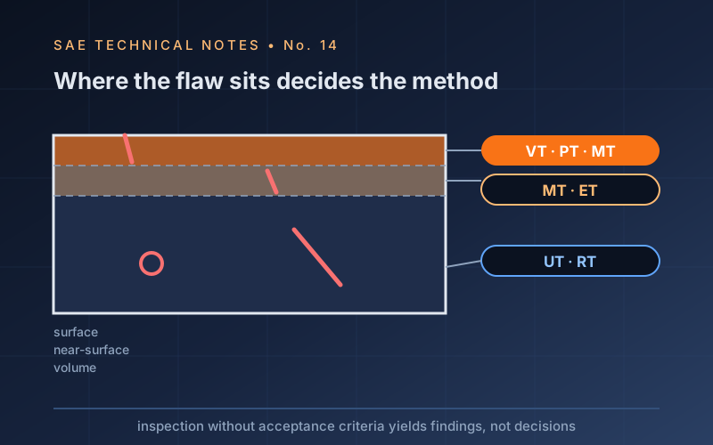
Non-destructive testing is the collective name for the methods that find discontinuities in and on a component without taking it out of service. Inspection alone, however, produces no result: whether a discontinuity counts as a defect is decided by an acceptance criterion agreed beforehand. And the method is chosen by the defect itself — where it sits, what type it is and which way it faces.
What this note covers
- The logic of method selection: defect location, type and orientation
- Visual (VT) and penetrant (PT) testing: their strengths and hard limits
- Magnetic particle (MT): why two perpendicular directions and why only ferromagnetic materials
- Eddy current (ET): penetration depth, coating thickness and alloy sorting
- Ultrasonic (UT): reading an A-scan, PAUT and TOFD, testability in coarse-grained material
- Radiography (RT): image quality with IQIs, orientation dependence, radiation safety
- Why UT and RT are not interchangeable — a defect orientation comparison
- Probability of detection (POD), personnel qualification (ISO 9712) and report content
Inspection Is a Decision Tool
Non-destructive testing does not make a part good; it tells you whether the part is acceptable against a stated criterion. Every method has a different sensitivity, a different orientation preference and a different blind spot, so the question is never “shall we inspect?” but “which defect, at which location, of which size, must be found — and which method can actually find it?”
The Logic of Method Selection: Location and Orientation
Two questions settle most choices. Is the defect at the surface or in the volume? Surface and near-surface flaws are found by visual, penetrant, magnetic particle and eddy current testing; internal flaws need ultrasonic or radiographic testing. How is the defect oriented? Radiography sees volumetric defects (porosity, slag) well and can completely miss a tight planar crack lying across the beam; ultrasonic testing is the opposite — excellent on planar defects aligned to reflect the beam, less informative on scattered porosity. Lack of fusion in a weld is a planar defect: it is a UT problem, not an RT problem.
Surface Methods
Visual testing (ISO 17637) is the cheapest and most underrated method. With adequate light, access, a gauge and a trained eye it finds undercut, misalignment, profile errors and gross cracking — and it is a prerequisite for everything that follows.
Penetrant testing (ISO 3452) draws a coloured or fluorescent liquid into surface-breaking discontinuities by capillary action. It works on any non-porous material, including austenitic stainless and aluminium, but only on defects open to the surface and only on a clean surface — blasting or machining can smear a crack closed and hide it.
Magnetic particle testing (ISO 17638 / ISO 9934) magnetises a ferromagnetic part and reveals flux leakage at surface and slightly subsurface defects. It is faster and more sensitive than PT, and it works through thin coatings.
Eddy current testing (ISO 15549) induces currents in conductive material and senses the disturbance. It is fast, non-contact and well suited to tube inspection, surface cracks and sorting of material or heat treatment condition — but it is sensitive to geometry, lift-off and conductivity, so it needs careful calibration on representative standards.
Volumetric Methods
Ultrasonic testing (ISO 16810; welds ISO 17640) sends a high-frequency pulse into the material and times the echoes. It gives depth information, needs access from only one side, and detects planar defects superbly. It depends heavily on operator skill, surface condition and couplant, and it struggles with coarse-grained materials such as austenitic welds and castings. Phased array and time-of-flight diffraction (TOFD) add imaging and reliable sizing — and, importantly, a permanent record.
Radiographic testing (ISO 17636) images density differences through the section. It produces an intuitive, archivable record that non-specialists can read, and it is the traditional choice for castings and for weld porosity and inclusions. The costs are radiation safety, exclusion zones, exposure time, and insensitivity to tight planar flaws.
Comparison
| Method | Finds | Misses / limits | Notes |
|---|---|---|---|
| VT | Surface geometry, visible cracks, profile | Anything not visible | Cheapest; always first |
| PT | Surface-breaking cracks, any non-porous material | Subsurface defects; needs clean, open surfaces | Consumables, cleaning, waste |
| MT | Surface and near-surface cracks | Non-ferromagnetic materials | Two field directions; demagnetise after |
| ET | Surface cracks, tubes, sorting | Depth limited; geometry sensitive | Fast, automatable |
| UT | Internal planar defects, thickness, depth | Coarse grain, complex geometry, near-surface dead zone | Operator dependent; phased array gives records |
| RT | Volumetric defects, an archivable image | Tight planar cracks, thick sections | Radiation protection governs planning |
What “Clean” Means: Probability of Detection
Detection is statistical, not binary. A POD curve describes the probability of finding a defect as a function of its size for a given method, procedure and inspector. Engineering uses it honestly by designing around the size that can be found: the damage tolerance approach assumes an undetected crack just below the detection threshold and sets the inspection interval so that it cannot grow to critical size before the next inspection. That is the bridge between NDT and fracture mechanics.
People, Procedures and Acceptance
- Qualification of personnel: EN ISO 9712 levels 1–3 — the method is only as good as the operator, and level 3 writes the procedures.
- Written procedure: technique, equipment, calibration blocks, scanning plan, sensitivity setting and acceptance criteria, agreed before the work starts.
- Acceptance levels: for welds, EN ISO 5817 quality levels B / C / D, chosen for the application; the same indication can be acceptable in one joint and rejectable in another.
The technical note below (A4 PDF, in Turkish) develops these subjects in depth with original diagrams prepared for this series.