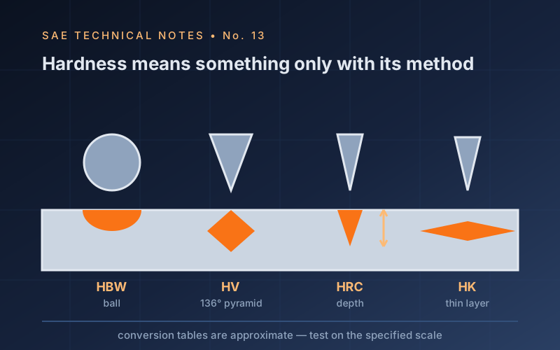
Hardness is defined as a material's resistance to permanent indentation — but that resistance depends on which indenter, which load and how the measurement is made. There is therefore no single absolute definition, and a hardness value is always written together with its method: 220 HV10, 45 HRC, 180 HBW 2.5/187.5. Even so it remains the most widely used test in industry: fast, cheap, almost non-destructive, and the most practical check on heat treatment, welding and surface engineering.
What this note covers
- Brinell, Vickers, Rockwell and Knoop: indenter, load, measured quantity and formulae
- The Rockwell scale table (HRC, HRB, HRA, superficial N scales) and their valid ranges
- Portable methods: Leeb, UCI and the limits of field measurement
- Which method for which situation — a selection table
- The two critical limits of conversion tables (ISO 18265 / ASTM E140)
- Hardness versus tensile strength: Rm ≈ 3.3 × HV, and where it does not apply
- Indentation spacing, edge distance and minimum specimen thickness rules
- Hardness profiles: case depth (CHD), nitriding depth and HAZ traverses in welds
Hardness Is Not a Material Constant
Hardness is the resistance of a surface to permanent indentation under a defined indenter, load and dwell time. Change any of those three and the number changes. That is why a hardness value without its method is not a measurement: 350 HV10 is a statement; “350 hardness” is not.
The Four Classical Methods
Brinell (EN ISO 6506 / ASTM E10) presses a tungsten carbide ball and measures the diameter of the impression. The large indentation averages over a coarse structure, which makes it the natural method for castings, forgings and unmachined material — and unsuitable for thin parts, hardened surfaces or small sections.
Vickers (EN ISO 6507 / ASTM E92, E384) uses a 136° diamond pyramid. One continuous scale covers everything from soft metals to carbides, and the geometry is self-similar, so results at different loads are comparable. With low loads (HV0.1–HV1) it becomes microhardness: the method for case depth traverses, individual phases and thin layers.
Rockwell (EN ISO 6508 / ASTM E18) measures the depth difference between a preload and a main load, reading directly from the instrument — fast, which is why it dominates production control. HRC (diamond cone, 150 kgf) is valid from roughly 20 to 70 HRC; HRB (1.588 mm ball, 100 kgf) covers softer materials.
Knoop (ISO 4545 / ASTM E384) uses an elongated diamond that produces a shallow, long impression — the choice for very thin layers, brittle materials and measurements close to an edge.
Portable Methods
Large or installed parts cannot be brought to a bench tester. Leeb (rebound) instruments measure the velocity ratio of an impacting body and need sufficient mass and a smooth surface — thin or light parts must be coupled to a heavy support. UCI devices measure the frequency shift of a vibrating rod loaded with a Vickers diamond; they are sensitive to surface roughness and to the material’s elastic modulus, so they require calibration on the actual material. Both convert internally to a conventional scale, which means they inherit all the limitations of conversion.
Conversion Tables and Their Danger
Conversion between scales (ISO 18265 / ASTM E140) is empirical and material dependent. A table derived for unalloyed steel does not hold for austenitic stainless steel, cast iron, nickel alloys, aluminium or cold-worked material. Converted values accumulate error in the direction nobody checks: a part can be rejected for failing a converted limit it would have passed when measured in the specified scale.
The practical rule is simple: specify the method the part will be measured in, and if a conversion must be used, state which standard and which material group it comes from.
Hardness and Tensile Strength
For unalloyed and low-alloy steels the familiar approximation Rm ≈ 3.3 × HB (MPa) is useful for an estimate, nothing more. It fails for cold-worked, austenitic, cast and non-ferrous materials, and it says nothing about yield strength, ductility or toughness — the properties that usually decide whether a part is fit for service.
Sources of Error and the Geometry Rules
| Source | Effect and remedy |
|---|---|
| Surface condition | Scale, decarburisation, grinding burn or roughness give false readings — prepare the surface and remove the affected layer |
| Thickness | The specimen must be at least 8–10 times the indentation depth; otherwise the anvil shows through |
| Spacing | Indentations must be at least 3–4 diameters apart and from the edge, or the work-hardened field of the previous one is measured |
| Curvature | Readings on curved surfaces require the correction factors given in the standard |
| Support and alignment | A part that moves or sits at an angle under load reads low; fixturing is part of the method |
| Calibration | Daily verification on reference blocks of the relevant range (ISO 6506-3 / 6507-3 / 6508-3) |
Hardness Profiles and Case Depth
For surface-hardened parts a single reading is meaningless; a microhardness traverse on a prepared perpendicular section is required. The limit is defined by convention: case hardening depth (CHD) to 550 HV1 for carburised parts (EN ISO 2639 / ISO 18203), nitriding hardness depth (NHD) at core hardness plus 50 HV, and surface hardening depth (SHD) for induction and flame hardening at 80% of the minimum surface hardness. Quoting a case depth without naming the criterion invites a dispute that no later measurement can settle.
The technical note below (A4 PDF, in Turkish) develops these subjects in depth with original diagrams prepared for this series.