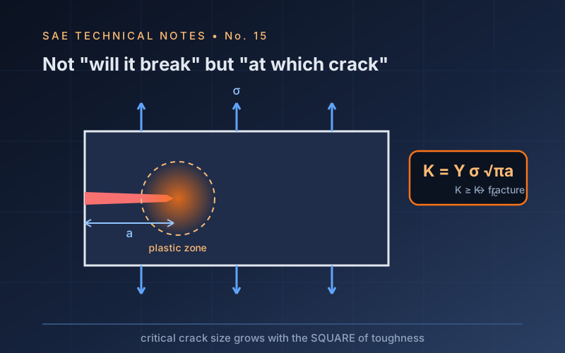
Classical strength analysis asks a single question: does the stress exceed the strength? That question assumes a flawless material, yet real components always contain a discontinuity. Fracture mechanics changes the question to: at what stress will this component fail with a crack of this size? Stress, crack size and fracture toughness are thereby joined in one equation — given any two, the third follows. This is the basis of modern failure analysis and of damage-tolerant design.
What this note covers
- The stress intensity factor K = Y·σ·√(πa) and the three loading modes
- Fracture toughness KIc, the thickness effect and the plane strain requirement
- The crack tip plastic zone and the validity limit of the linear elastic approach
- Critical flaw size calculation — with a worked example
- Elastic-plastic parameters: CTOD and the J integral, links to BS 7910 / API 579
- Ductile-brittle transition, the Charpy curve and EN 10025 quality grades (JR, J0, J2, K2)
- What lowers toughness: temperature, loading rate, thickness, notches, temper embrittlement
- The Paris law bridge to fatigue and setting inspection intervals
Why a Strength Calculation Is Not Enough
Classical design compares a nominal stress with yield or tensile strength. That comparison assumes the material is continuous — but real components contain cracks, inclusions, weld defects and machining marks. Fracture mechanics answers the question strength calculation cannot: given a crack of this size, at this stress, in this material, does the crack grow stably or does the component break?
The Stress Intensity Factor K
The stress field at a crack tip is described by a single parameter:
K = Y σ √(πa)
where σ is the nominal stress, a the crack size and Y a geometry factor. Fracture occurs when K reaches the material’s fracture toughness KIC. Three consequences follow immediately, and they are the practical heart of the subject:
- Because K depends on √a, doubling the crack length raises K by only 41% — but quadrupling it doubles K. Crack growth is dangerous because it accelerates, not because it is linear.
- For a given material and stress there is a critical crack size ac = (KIC / Yσ)² / π. That number, not a safety factor, is what an inspection plan has to beat.
- Toughness is a material property with units of MPa√m, and it falls with decreasing temperature, increasing strength and increasing section thickness.
Plane Strain, Plane Stress and Thickness
A thin section deforms freely through its thickness (plane stress): the plastic zone is large and the apparent toughness is high. A thick section constrains that deformation (plane strain): the plastic zone is small, the state of stress is triaxial, and toughness falls to the conservative lower-bound value KIC. This is why a valid KIC test (ASTM E399 / ISO 12737) imposes minimum thickness requirements — and why a thin-sheet toughness value must never be used to justify a thick forging.
When the Material Is Too Tough for K: CTOD and J
In ductile structural steels the plastic zone is too large for linear elastic analysis, and K becomes invalid. Two elastic–plastic parameters take over. CTOD — crack tip opening displacement, measured in millimetres (BS 7448 / ISO 12135) — is widely used for welded steel structures and offshore work. The J-integral (ASTM E1820), an energy parameter, is the general formulation; in the elastic regime J and K are directly related. Modern test standards measure a resistance curve (J–R or CTOD–R) rather than a single number, because in tough materials the crack grows stably before instability.
The Transition Temperature
Body-centred cubic steels change behaviour over a narrow temperature range: above it they fail by ductile tearing with high energy absorption, below it by cleavage with almost none. Charpy testing maps this transition cheaply and is used for screening and acceptance; fracture toughness testing quantifies it for design. The Master Curve approach (ASTM E1921) ties the two together statistically through the reference temperature T0. The practical lesson is that a material specification without a temperature is incomplete — the grade designation S355J2 contains its test temperature for exactly this reason.
Fatigue Crack Growth: the Paris Law
Fracture mechanics also describes how fast an existing crack grows under cyclic loading:
da/dN = C (ΔK)m
The curve has three regions: a threshold ΔKth below which cracks effectively do not propagate; a straight (Paris) region where the law applies, with m typically 3–4 for steels; and an acceleration region as Kmax approaches KIC. Integrating the Paris law from the detectable crack size to the critical crack size gives the remaining life — the calculation behind every damage-tolerant inspection interval.
Damage Tolerance in Practice
The design philosophies differ in what they assume:
| Philosophy | Assumption | Consequence |
|---|---|---|
| Safe life | The part contains no cracks; it is retired after a set life | Simple, but conservative and blind to manufacturing defects |
| Fail safe | Redundant load paths carry the load if one member fails | Structural weight penalty |
| Damage tolerant | A crack just below the inspection threshold already exists | Inspection intervals computed from crack growth; the aerospace standard |
The chain is explicit: NDT sets the detectable size, the Paris law sets the growth rate, toughness sets the critical size, and the inspection interval is a fraction of the time between the two.
What Raises and Lowers Toughness
- Raise it: fine grain size, clean steel (low S and P, controlled inclusions), tempered martensitic or bainitic structures, nickel additions for low-temperature service.
- Lower it: increasing strength (the classic strength–toughness trade-off), falling temperature, coarse grains, temper embrittlement, hydrogen, irradiation, triaxial constraint from thick sections and sharp notches.
Which is why the toughest design decision in a fracture-critical part is usually to stop increasing strength.
The technical note below (A4 PDF, in Turkish) develops these subjects in depth with original diagrams prepared for this series.