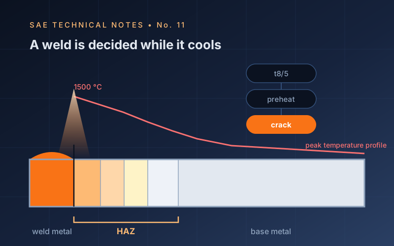
Welding is not an assembly operation that joins two parts: a small casting takes place in the molten zone, and an uncontrolled heat treatment in the region right next to it. A welded joint is therefore no longer a single material — cast structure, a coarse-grained region, a fine-grained region and untouched parent metal all sit side by side in the same section. Almost every welding failure starts in these transition zones.
What this note covers
- Weld zones: weld metal, fusion line and the HAZ sub-zones
- Heat input calculation, process efficiencies and the t8/5 cooling time
- Cold cracking: the four conditions, preheat and low-hydrogen consumables
- Hot cracking: sulphur and phosphorus segregation, bead shape, crater cracks
- Defect–cause–remedy table and which inspection method finds which defect
- Residual stresses, distortion and stress relief
- Sensitisation and the δ-ferrite balance in stainless steel; oxide and porosity in aluminium
- WPS/WPQR, welder qualification and quality level standards
A Weld Is a Casting and a Heat Treatment, Performed in Place
Welding melts a small volume of metal and lets it solidify against a massive cold body, then heat treats a band of material around it with a thermal cycle nobody designed. Everything the welding engineer deals with — cracks, softening, hardening, distortion — follows from that single sentence. The weld metal has a cast solidification structure; the heat-affected zone (HAZ) has a structure determined by peak temperature and cooling rate; the parent metal is untouched.
The Zones of a Weld
| Zone | Peak temperature | Structure and behaviour |
|---|---|---|
| Weld metal | Above melting | Cast, columnar grains; composition is a mix of consumable and dilution from the parent |
| Coarse-grained HAZ | > 1100 °C | Grain growth; most prone to hardening and to brittle fracture |
| Fine-grained HAZ | 900–1100 °C | Refined by recrystallisation — often the best properties in the joint |
| Intercritical / subcritical | 700–900 °C / below | Partial transformation; in quenched-and-tempered steels, local softening |
The controlling parameter is t8/5 — the time to cool from 800 to 500 °C. Short times (thick section, low heat input, no preheat) harden the HAZ; very long times coarsen it and lower toughness. EN 1011-2 turns this into practice through heat input, preheat and interpass temperature recommendations.
Cold Cracking (Hydrogen-Induced Cracking)
Four conditions must coincide: a susceptible (hardened) microstructure, dissolved hydrogen, tensile restraint stress, and a temperature below roughly 150 °C. Remove any one and the crack does not form — which is exactly how it is prevented: preheat to slow cooling and let hydrogen diffuse out, use low-hydrogen consumables that are dried and correctly stored, clean oil, rust and moisture from the joint, reduce restraint, and apply post-weld heat soaking where the section demands it. Cold cracks are delayed: they appear hours after welding, so the inspection timing is part of the procedure.
Hot Cracking (Solidification Cracking)
Hot cracks form while the weld is still partly liquid, when low-melting films — sulphur and phosphorus rich in steels — are pulled apart by contraction. They prefer deep narrow beads (an unfavourable depth-to-width ratio), high restraint and craters at the end of a run. Remedies are compositional (low S and P, manganese to tie up sulphur), geometrical (wider, shallower beads) and procedural (crater filling, controlled travel speed).
Austenitic Stainless Steel and Aluminium
In austenitic stainless steels a small controlled amount of delta ferrite (roughly 3–10 FN, read from the Schaeffler–DeLong or WRC-1992 diagram using Cr and Ni equivalents) prevents solidification cracking — too little cracks, too much embrittles in service. The second classic problem is sensitisation: holding 450–850 °C precipitates chromium carbides at grain boundaries and strips the adjacent metal of corrosion resistance, producing intergranular attack next to the weld (“weld decay”). Low-carbon (304L, 316L) or stabilised (321, 347) grades, and limited heat input, are the answer.
Aluminium brings its own list: the tenacious oxide film must be removed mechanically or by the arc’s cleaning action, high thermal conductivity demands much higher heat input, hydrogen from moisture causes porosity, and the HAZ of a heat-treatable alloy (6xxx, 7xxx) loses its temper — the joint is softer than the parent and must be designed that way.
Defects, Causes and Prevention
| Defect | Typical cause | Prevention / detection |
|---|---|---|
| Lack of fusion | Low heat input, wrong torch angle, dirty joint | Procedure and technique; detected by UT, not by RT |
| Incomplete penetration | Root gap and preparation, travel speed | Joint design, back gouging; UT / RT |
| Porosity | Moisture, draught disturbing the shielding gas, contamination | Dry consumables, gas flow and wind screens; RT |
| Slag inclusion | Incomplete interpass cleaning | Cleaning between runs; RT |
| Undercut | Excessive current, wrong angle | Parameter control; VT with a gauge |
| Cracks | Hydrogen, restraint, solidification films | Preheat, consumable control, bead geometry; MT / PT / UT |
Residual Stress and Distortion
Contraction is restrained, so every weld leaves tensile residual stress near yield in the joint, balanced by compression elsewhere — which is why fatigue of welded structures is assessed by stress range and detail category rather than by mean stress. Distortion is controlled by balanced welding sequences, fixtures, back-step techniques and minimum necessary weld volume; stress relief heat treatment is the remedy when the service or the subsequent machining demands it.
Qualification and Inspection
A welded joint is only as reliable as the system behind it: procedure qualification to EN ISO 15614, welder qualification to EN ISO 9606, acceptance levels to EN ISO 5817, and non-destructive testing to the matching ISO methods (17637 visual, 3452 penetrant, 17638 magnetic particle, 17640 ultrasonic, 17636 radiographic).
The technical note below (A4 PDF, in Turkish) develops these subjects in depth with original diagrams prepared for this series.