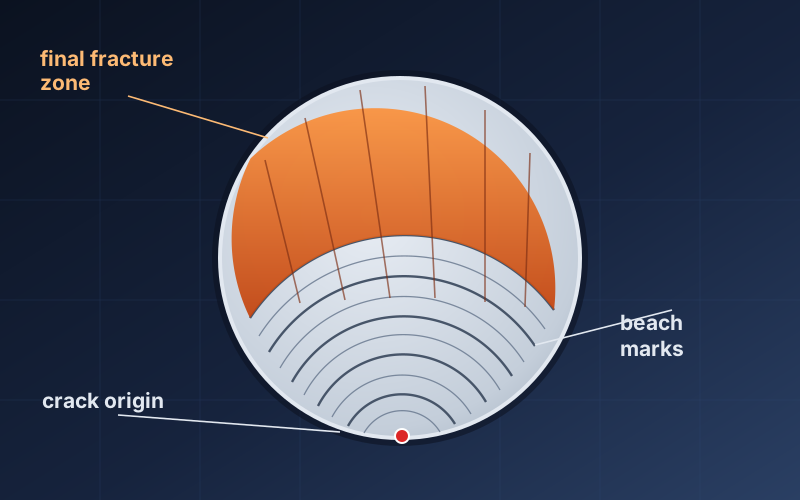
A machine component that breaks in service carries the story of its failure on the fracture surface: where the crack started, how it propagated, the type and magnitude of the load, and even manufacturing defects in the material can be read from it. Failure analysis evaluates these marks with systematic methods to establish the root cause — the goal is not to assign blame, but to prevent the failure from recurring.
What this note covers
- Fracture modes: ductile, brittle, fatigue and environmentally assisted cracking
- Macro fractography: beach marks, ratchet marks, chevron patterns and inferring stress level from the final fracture area
- Micro fractography (SEM): dimples, cleavage, striations and common interpretation pitfalls
- Laboratory techniques: chemical analysis, metallography, hardness, SEM/EDS and measurement reliability
- Root cause families: design, material, manufacturing and service related failures; reporting principles
What a Failure Investigation Is For
A failure investigation is not about assigning blame; it is about producing a single, consistent scenario that explains every observation, so that the same part does not break again. A broken component carries its own history on its fracture surface — where the crack started, how it grew, how highly it was stressed and often how long it took. The work consists of reading that record without destroying it.
Method: Stages From Cheap to Irreversible
The sequence matters, because each step decides where the next one takes its sample, and because the irreversible operations (cutting, etching, mechanical testing) can only be done once.
- Background: service conditions, load spectrum, running hours or cycles, maintenance history, and what happened at the moment of failure.
- Preserve the evidence: do not touch the fracture surface and never fit the two halves back together — that single action crushes the features that identify the origin. Photograph before cleaning.
- Visual and macro examination: perpendicular, scaled photographs; map the origin, the propagation direction and the final fracture zone.
- Non-destructive testing: penetrant, magnetic particle, ultrasonic or radiographic inspection for secondary cracks and internal defects.
- Chemical analysis: is the material what the drawing specified?
- Metallography: sections taken from the suspect area — microstructure, case depth, inclusions, grain structure.
- Hardness and mechanical tests: compared against the specification.
- SEM / EDS: micro-scale confirmation of the mechanism and identification of foreign elements.
- Synthesis and report: all findings combined into one scenario. If a finding contradicts the scenario, the scenario changes — the finding is never hidden.
Fracture Types
| Type | Macro appearance | Micro mechanism | Typical condition |
|---|---|---|---|
| Ductile | Visible plastic deformation, necking, 45° shear lip, dull fibrous surface | Microvoid coalescence (dimples) | Overload, tough material |
| Brittle | No deformation, flat bright crystalline surface, chevron marks | Cleavage or intergranular separation | Impact, low temperature, high hardness, notch |
| Fatigue | Flat propagation zone with beach marks, small final fracture area | Cyclic slip, striations | Repeated load far below static strength |
| Environmental | Discolouration, branched cracks, corrosion products | SCC, hydrogen embrittlement, corrosion fatigue | Corrosive medium plus tensile stress |
The majority of service failures are fatigue: machines are rarely overloaded once, but they are loaded and unloaded millions of times. That is why macro fractography concentrates on reading fatigue marks.
Macro Fractography: Reading the Surface
Beach marks are the arrest lines of the crack front; they curve around the origin, so they point back to where the failure started. Ratchet marks — steps between adjacent origins — count the starting points: many origins mean a high stress concentration or a very high nominal stress.
The ratio of the final fracture area to the total section is the single most informative measurement on the surface. A small final zone means the part was lightly stressed and the crack grew for a long time; a large final zone means the nominal stress was high. Combined with the number of origins, this separates a design problem from an overload event before any laboratory work begins.
Micro Fractography and Its Traps
In the SEM, dimples indicate ductile tearing, cleavage facets with river patterns indicate brittle transgranular fracture, and smooth grain facets indicate intergranular failure — which always demands an explanation: temper embrittlement, hydrogen, SCC, creep or grain-boundary films. Striations confirm fatigue but are frequently obliterated by rubbing, corrosion or post-failure damage, so their absence proves nothing. EDS identifies foreign elements (chlorine, sulphur, sodium) that point to the environment, but it analyses what is on the surface now — including contamination introduced after the failure.
Root Cause Families
- Design: stress concentration, insufficient section, wrong material or heat treatment specified, no corrosion allowance.
- Manufacturing: casting or forging defects, weld defects, heat treatment errors, machining marks and grinding burns.
- Material: wrong grade supplied, inclusions, decarburisation, non-conforming properties.
- Assembly and service: misalignment, incorrect preload, overload, inadequate lubrication, an environment nobody specified.
Reporting
A defensible report separates observations from interpretation, states the methods and standards used, shows scaled images, and ends with corrective actions that are specific enough to implement. Any finding that does not fit the conclusion is reported with its explanation — that is what distinguishes an investigation from an argument.
The technical note below (A4 PDF, in Turkish) develops these subjects in depth with original diagrams prepared for this series.